I have a broken SD Connect C4 on the bench and was asked to try to fix it. Without batteries inserted my bench power supply shows the set 13.8V and around 400 mAh. As soon as batteries are inserted the voltage goes down to 4.4V.
You set your bench supply 13.8 V and the current consumption is about 400mA. That is about right. The insertion of batteries should not make any difference.
What do you mean the voltage goes down to 4.4V? Is it the bench supply voltage going down?
Further to what I said above your current consumption should fluctuate from about 400 to 500 mA to about 1.4A at 12.5V supply voltage. That is if your batteries are not fully charged. These are charge pulses charging the batteries. That is assuming that you have a fully working charge circuit which seems to be rare. The charge pulses are 1 second long.
Depending on the current limit setting on your power supply it is possible that the supply runs into current limit during the peak current and reduces the output voltage. Increase the current limit value to >2Amp. That should fix it.
What part of the board is the charge sub system? I definitely see the fluctuation on the power supply. And what is the tiny PCB inside the battery clip for?
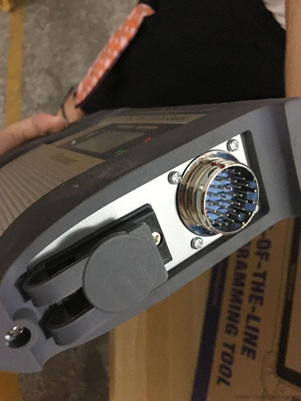
The parts of the charge system are on the top side of the main board (opposite to the relay side) close to the board that could be called the mother board or whatever. It consist of a timed regulated current charging circuit. The current is limited to 1Amp. The switcher involved in this circuit is the 16 pin Lt1976 chip, it fails frequently. It is located close to the 5 pin connector. Easy to buy but not so easy to replace since it has a center ground plane which unless you know how to solder with a hot air gun, cannot be mounted. Additional components for this circuit are mounted on the opposite side of the PCB. Further down the board are some changeover circuits.
The 1 sec timing signal is applied to pin15 of this chip.
The PCB inside the battery clip is a degree C temperature sensor LM50CIM, its case marking should be T5C. In order to check this board you can measure the voltages on on the 5 pin connector. The first pin should read about 0.75V at 25C, 2nd pin 5V, 3rd pin Gnd, 3th and 5th pin are the battery voltage.
To check this circuit properly you should measure the voltages above and also measure the 1 second current peak which must be 1Amp at 12.5V. If it is less, about half, there is a problem with the LT1976, probably failed FET’s inside the chip.
This is for your information.
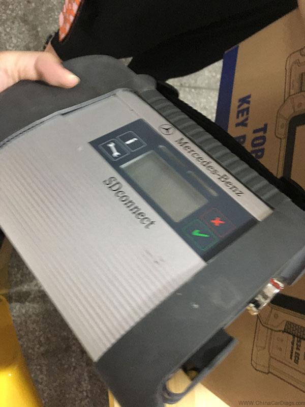
Forget cheap SDconnect C4 crappy.
If you don’t wanna spend a lot with Star Diagnostic C4, clones can be your way to go.
But pls go to a site that is reliable and with good reviews, and confirm its functionality of SD connect c4.
I mean, even the clone, the quality makes difference from different vendors.
As far as i know, there are more than 3 Chinese factories producing c4 but only one or two is high quality and with good tech support. Chinacardiags.com is the one i’m using most. Refundable if it cannot work.
I have both the genuine and clone
See my clone off obd2tool.com – it never upsets me.