This application allows you to pair up the Autel Maxisys Display Tablet with the VCI device, either the J2534 Programming Device or the Bluetooth Diagnostic Interface, and to check the communication status.
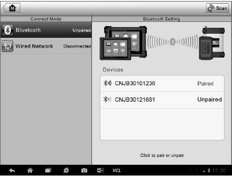
1. Connection Mode – there are two connection modes available for selection. The connection state is displayed alongside.
(1) Bluetooth Paring – when paired to a Bluetooth device, the connection state displays as Paired; otherwise it displays as Unpaired.
(2) Wired Network Connection (for J2534 ECU Programming Device only) – when connected to a Local Area Network, the connection status displays as Connected; otherwise it displays as Disconnected.
(3) Select a connection mode to manage and set up connection.
2. Settings – this section allows you to manage wireless pairing or set up network connection.
(1) Bluetooth Setting – searches and displays the type and a partial serial number for all of the devices available for pairing. Tap a required device to start pairing. The Bluetooth status icon displayed to the left of the device name indicates the received signal strength.
(2) Ethernet Setting – allows you to perform network configuration.
Bluetooth Pairing
The VCI device needs to be either connected to a vehicle or to an available power source, so that it is powered up during the synchronization procedure.Make sure the MaxiSys Display Tablet has a charged battery or is connected to an AC/DC power supply.
To pair the VCI device with the Display Tablet
1. Power on the MaxiSys Display Tablet.
2. Connect the 26-pin end of the data cable to the J2534 ECU Programming Device’s vehicle data connector.
3. Connect the 16-pin end of the data cable to the vehicle data link connector (DLC).
4. Tap the VCI Manager application on the MaxiSys Job Menu of the display tablet.
5. Select Bluetooth from the connection mode list.
6. Tap the Scan button at the top right corner. Now the device starts searching for available pairing units.
7. Depending on the VCI type you use, the device name may display as Maxi suffixed with a serial number. Select the required device for pairing.
8. When paring is successfully done, the connection status displayed to the right of the device name is shown as Paired.
9. Wait a few seconds, and the VCI button on the system Navigation bar at the bottom of the screen shall display a green tick icon, indicating the display tablet is connected to the VCI device.
10. Tap the paired device again to unpair it.
11. Tap the Back button on the top left to return to the MaxiSys Job Menu.
NOTE: A VCI device can be paired to only one Display Tablet each time, and once it’s been paired, the device will not be discoverable for any other unit.
Wired Network Connection
The Wired Network is applied for connecting the MaxiSys Display Tablet with J2534 ECU Programming Device or to an existing LAN. This section describes connecting the display tablet with the J2534 ECU Programming Device through the Ethernet cable.
The Autel MaxiFlash Elite J2534 Device needs to be either connected to a vehicle or to an AC/DC power source, so that it is powered up when communicating with the display tablet. Make sure the MaxiSys Display Tablet has a charged battery or is connected to an AC/DC power supply.
To connect the display tablet with the J2534 ECU Programming Device through wired network
1. Power on the MaxiSys Display Tablet.
2. Connect the 26-pin end of the data cable to the J2534 ECU Programming Device’s vehicle data connector.
3. Connect the 16-pin end of the data cable to the vehicle data link connector (DLC).
4. Connect the MaxiSys Display Tablet to the programming device with the accompanied Ethernet serial cable.
5. Tap the VCI Manager application on the MaxiSys Job Menu of the display tablet.
6. Select Wired Network from the connection mode list. Now the Ethernet Setting interface displays.
7. Select a connection type:
DHCP – obtains the LAN IP address automatically
Manual – allows you to enter IP address manually
8. If Manual is selected, you need to set the IP address on your own.
NOTE: If you are not sure about the specific IP address values, please contact your network administrator.
9. Tap Apply to set up the wired network connection.
10. Tap the Back button on the top left to return to the MaxiSys Job Menu.
When the wired network is successful connected, the connection status is displayed as Connected, and the two status lights at the corners alongside the Ethernet Ports on the display tablet illuminate. The solid amber light indicates steady connection, and the flashing green light indicates active communication, between the units. The Autel Scanner VCI navigation button at the bottom bar shall display a green tick icon after a few seconds, indicating the MaxiSys Pro diagnostic platform is ready to perform vehicle diagnosis.