Using the HTTP Interface
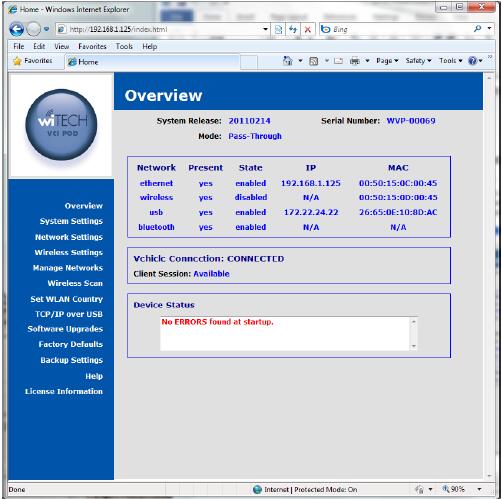
Shown below is the main screen for the device configuration web site. The Overview page will provide you with version information for the hardware and software and the device serial number.
System Setting
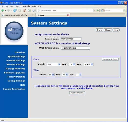
You can assign a name to the witech Micropod 2 that will be shown on the device discovery utility screen in place of the default serial number. You may also wish to set the date and time on the device.
Device Name Assign a name to the device. This name will appear on the device locator utility screen that shows the devices available on the network. Click on the Save button to store the new device name.
Work Group Assign a work group name to the device. Click on the Save button to store the new device name.
Date & Time Set the date and time for the device. Use the drop down
selection boxes to select the current date and time. Click on the Set Date & Time button to store the new date and time.
Reboot Use this button to force the device to perform a system reboot.
Device
Network Settings
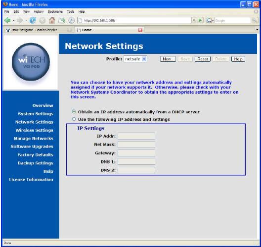
You can choose to have your network address and settings automatically assigned if your network supports it. Otherwise, please check with your Network Systems Coordinator to obtain the appropriate settings to enter on this screen.
Automatic or Static To have an automatically assigned network address choose Obtain an IP address automatically from a DHCP server
If you will be using static IP addressing for the device, choose Use the following IP address and settings
IP Settings
IP Address Enter the IP address assigned to this device, typically provided to you by your network or system administrator, for example 192.168.1.100.
Net Mask Enter the network address mask used by the device,typically provided to you by your network or system administrator, for example 255.255.255.0.
Enter the IP address for the machine on your network that Gateway acts as a gateway to other networks. Your network or system administrator typically provides this address, for example 192.168.1.1, to you.
DNS1 Enter the IP address for the machine that should be used as the primary Domain Name Server. If your network is configured to use DNS your network or system administrator will provide this to you.
DNS2 Enter the IP address for the machine that should be used as the secondary Domain Name Server. If your network is configured to use DNS your network or system administrator will provide this to you.
You can choose to have your network address and settings automatically assigned if your network supports it. Otherwise, please check with your Network Systems Coordinator to obtain the appropriate settings to enter on this screen.
Automatic or Static To have an automatically assigned network address, choose Obtain an IP address automatically from a DHCP server.
If you will be using static IP addressing for the Device, choose Use the following IP address and settings.
IP Settings
IP Address – Enter the IP address assigned to this Device, typically provided to you by your network or system administrator, for example 192.168.1.100.
Net Mask – Enter the network address mask used by the Device, typically provided to you by your network or system administrator, for example 255.255.255.0.
Gateway – Enter the IP address for the machine on your network that acts as a gateway to other networks. Your network or system administrator typically provides this address, for example 192.168.1.1, to you.
DNS1 – Enter the IP address for the machine that should be used as the primary Domain Name Server. If your network is configured to use DNS your network or system administrator will provide this to you.
DNS2 – Enter the IP address for the machine that should be used as the secondary Domain Name Server. If your network is configured to use DNS your network or system administrator will provide this to you.
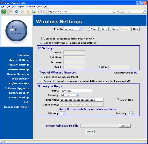
Type of Wireless Network – To connect your Device to the network via a wireless access point, choose Connect to an Access Point.
If you need to connect your Device directly to PC or some other computer, choose Connect to another computer using Adhoc network.
Security Settings
SSID – Enter the Service Set Identification that should be used by your Device to join a 802.11 wireless network.
Security – Select the encryption technique to be used when communicating on the wireless network. This must be the same as is being used by the access point or other computer you will be connecting to.
Enter Key – Enter the key to be used by the encryption software used when communicating on the wireless network. This key must match the key being used by the access point or other computer you will be connecting to.
Confirm Key – Re-enter the key to be used by the encryption software used when communicating on the wireless network. This is done to confirm the value since it is hidden on entry.
Key in HEX – Select this option if the value entered for the encryption key was entered using HEX values.
Edit Key – For security mechanisms that allow multiple keys, use this selection box to select the key that is to be edited.
Use Key – For security mechanisms that allow multiple keys, use this selection box to select the key that is to be used when communicating on the wireless network. If multiple keys are present, the one selected must match the key being used on the access point or other computer the automotive diagnostic equipment will be connecting to.
Miscellaneous Import Wireless Profile – Allow you to import a wireless profile that is provided by a network administrator or other system administrator. The profile must be provided in a file formatted specifically for this purpose.
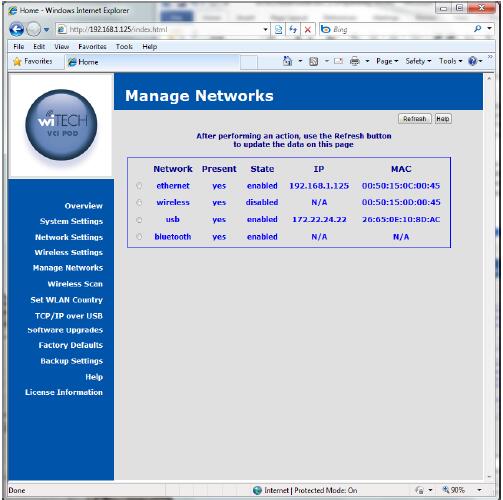
Manage Networks
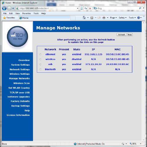
You will have one or more network interfaces on the device, such as Ethernet, WLAN, USB, and Bluetooth. Ethernet and WLAN interfaces can have one or more sets of configuration data, referred to as a profile. Profiles are manipulated on the Network and Wireless Settings pages. The Manage Networks page allows you to make a configuration profile active for an interface. You can restart the Ethernet interface, and stop/start/restart the WLAN interface. The USB interface can only be restarted as it is also present and active. The Bluetooth interface is provided via an optional wiTECH SmartCable. If present and enabled
This screen offers a button to restart the interface if some problem is encountered and customer support asks you to restart the interface.
Ethernet Adapter
The Ethernet network interface is always present and active on this device. The device is factory configured with a default profile that is initially set to obtain an IP Address via DHCP. You can change this profile on the Network Settings page.
Enable Button Enable the interface when it has been previously disabled
Disable Button Disable the interface, preventing any traffic across the interface
Restart Button This button can be used to restart the Ethernet network interface with the currently active profile settings.
Status Shows the current state of the interface, Active, Started, and Disabled
IP Address The IP address currently assigned to this device, either via
DHCP or static assignment. If no IP Address is listed the network connection may be down or the Ethernet cable might be unplugged.
Profiles A list of profiles containing configuration settings for the Ethernet network interface is provided here. The settings in use will be shown as Currently Active. Other available profiles will have a Make Active button next to the profile name that allows you to change the settings used by the Ethernet interface and restart the network.
Wireless Adapter (optional)
The OBD2 Scanner Wireless LAN network interface is a device hardware option. When it is present, a factory configured default profile initially set to obtain an IP Address via DHCP is provided. However, the access point and security information will need to be entered via the Wireless Settings page.
Enable Button – Enable the interface when it has been previously disabled
Disable Button – Disable the interface, preventing any traffic across the interface
Restart Button – This button can be used to restart the Wireless LAN network interface with the currently active profile settings.
Status – Shows the current state of the interface, Active, Started, and Disabled
IP Address – The IP address currently assigned to the WLAN interface, either via DHCP or static assignment. If no IP Address is listed the network connection may be down, the access point security settings are incorrect, or the wireless access point is unreachable.
AP Address – The access point hardware address is provided here. It is taken directly from the access point when a wireless
connection is established. If the address shows as all Os no connection is present.
Profiles – A list of profiles containing configuration settings for the Wireless LAN network interface is provided here. The settings in use will be shown as Currently Active. Other available profiles will have a Make Active button next to the profile name that allows you to change the settings used by the Wireless LAN interface and restart the network.
Bluetooth Adapter
The device can make a connection to a Bluetooth enabled PC. A zero configuration IP (ZCIP) address will be used. The Bluetooth and WLAN network interfaces cannot be used concurrently. Enabling one will force the other to be disabled.
Enable Button – Enable the interface when it has been previously disabled
Disable Button – Disable the interface, preventing any traffic across the interface
Restart Button – This button can be used to restart the Bluetooth network interface.
Status – Shows the current state of the interface, Active, Started, and Disabled
IP Address – The IP address currently assigned to the Bluetooth interface via ZCIP.
USB Adapter
The USB network interface is provided via the USB connector on the device. The connector can be found on the faceplate just below the antenna. The USB cable provided with the device when purchased should be used. Connect the miniconnector end to the device and the other end to a Windows PC which has the Bright Star Engineering Ethernet Gadget drivers installed. A DHCP server is provided on the device to assign an IP address to the PC when connected over the USB interface. Refer to the TCP/IP over USB web page description further on in this document for more information.
Restart Button – This button can be used to restart the USB network interface should a problem occur Status – Shows the current state of the interface, Active, Started, and Disabled
IP Address – The IP address currently assigned to the Bluetooth interface via static assignment.
Wireless Scan
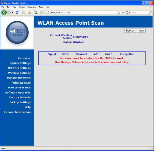
Use this utility to scan for available wireless networks at your location. Some networks may not be visible if the wireless access point(s) has been configured to not broadcast the SSID. Please note that the wireless interface on the device must be enabled for this feature to work.
TCP/IP over USB
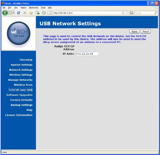
This page is used to configure the TCP/IP address to be used for the USB based network. This device can be connected directly to a Microsoft Windows PC with a USB cable. When connected, a TCP/IP network will be created between the device and the Windows PC over the USB cable. The TCP/IP address entered on this page will be assigned to the device and used to seed the DHCP address assigned to the Windows PC.
Factory Defaults
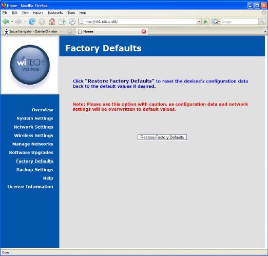
Use this page to reset the device configuration settings back to the factory default values. Note: Please use this option with caution, as configuration data and network settings will be overwritten to default values.
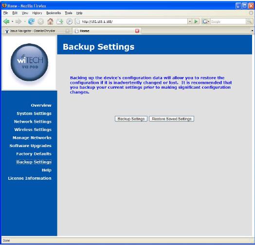
Backup Settings
Software
Software Upgrades
Using the HTTP Installer
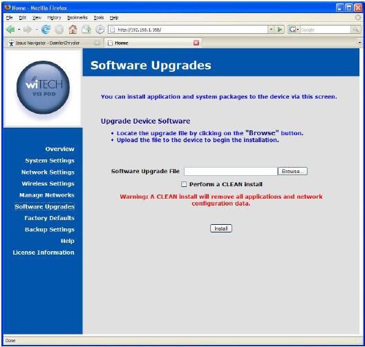
The Software Upgrades page on the device configuration web site allows you to install platform software and firmware upgrades. Use the Browse button on this screen to locate the software package on the local machine and click on the Install button to initiate the upload of the package file. The upgrade will be started automatically when the file is uploaded. Once the upgrade begins you will loose your browser connection to the device. The LED will be turned on to indicate the upgrade is being performed. The software upgrade notification screen will attempt to refresh to indicate the upgrade is complete.
If you wish to reset the device during the upgrade process, click on the checkbox labeled as Perform a CLEAN Install.
If a failure occurs during the upgrade, the LED will be turned on to indicate a problem exists. If this should occur follow the procedure outlined below.